|
Sangmin Sung Portfolio
|


|
|
Sangmin Sung Portfolio
|
|
Mechatronics at Cal Poly follows the learn by doing model. In this course each lab incorporates new driver and task files that will be used in the final term project. Mechatronics encompasses mechanical, electronic, controls, and programing in one area of study. This philosophy allows a designer to have ultimate consideration of the different aspects and subsystems of a particular design. Some examples of mechatronic applications are RC Cars, printers, vending machines, robotics, and cars. Below is a description of each of the labs conducted and the goals for each lab.
Lab 0 Fibonacci: A program using micro-python that will automatically calculate the fibonacci number at any valid index. Please click the Lab0 page on the left to learn more.
Lab 1 LED: A program using micro-python that will blink an LED using a PWM signal, in three different ways blink on/off, sinosidal, and saw tooth. Please click the Lab1 page on the left to learn more.
Lab 2 Encoder: A program using micro-python that will encompass three files to measure the current position and change in position of an encoder. Please click the Lab2 page on the left to learn more.
Lab 3 Motor: A program using micro-python that will encompass five files to run two motors at specfic duty cycle and at the same time measure each motors relaive position and angular velocity using the encoders. Please click the Lab3 page on the left to learn more.
Lab 4 Controller: A program using micro-python that will encompass seven files to run two motors to steady state using a closed loop controller to update the motors current angular velocity relative to its setpoint velocity. Please click the Lab4 page on the left to learn more.
Lab 5 Inertial Measurement Unit: A program using micro-python that will encompass two files to calibrate an Inertial Measurement Unit, and measure a balance boards relative orientation and display it in the form of Euler angles and angular velocity. Please click the Lab5 page on the left to learn more.
Final Project Ball Balancing Platform: A program that integrates all the hardware, drivers, and a system model together.The goal of this project is to combine all the hardware and software models to create a closed–loop control system capable of balancing the ball on the platform. Please click the Final Project page on the left to learn more.
A program that integrates all the hardware, drivers, and a system model together.The goal of this project is to combine all the hardware and software models to create a closed–loop control system capable of balancing the ball on the platform. This project essentially incorporates all the labs done thoughout the quarter into one final term project. Please click the Final Project page on the left to learn more.
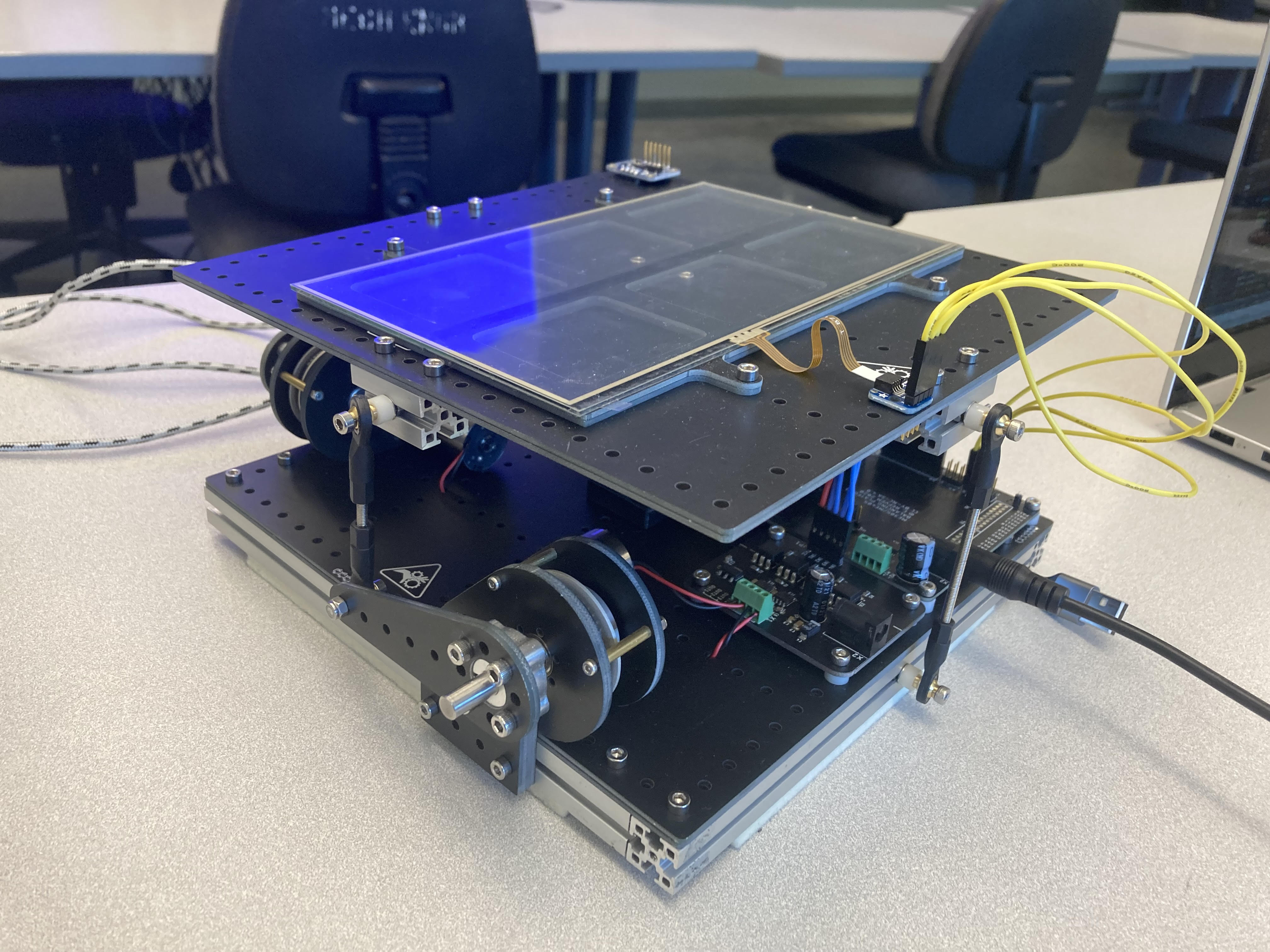
Below in Figure 1, depicts the ball balancer plateform and the various hardware elements that help make the ball balancer able to balance a ball on top. As you can see, there is a resistive touchpanel on top the varies postion of the ball in relation to voltage outputed from that panel. There is also two motors the move the panel up and down, and there is an IMU that depicts the current angle and angular velocity of of the panel. We used all these devices to implement closed loop feedback control to balance the ball and to actuate the motors to counter act the balls movement.
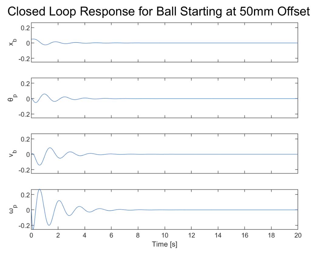
In order to implement closed loop control on this plateform, a simplier system modeling of the plateform was done in order to simulate the system response for any K. Below in figure 2, you can see the simulation results of the state vector, showing ball position, panel angle, ball velocity, and panel angular velocity against time. As you can see, all the signals die out due to the closed loop feedback and controller gain K that helps dictate the torque applied by the motor.
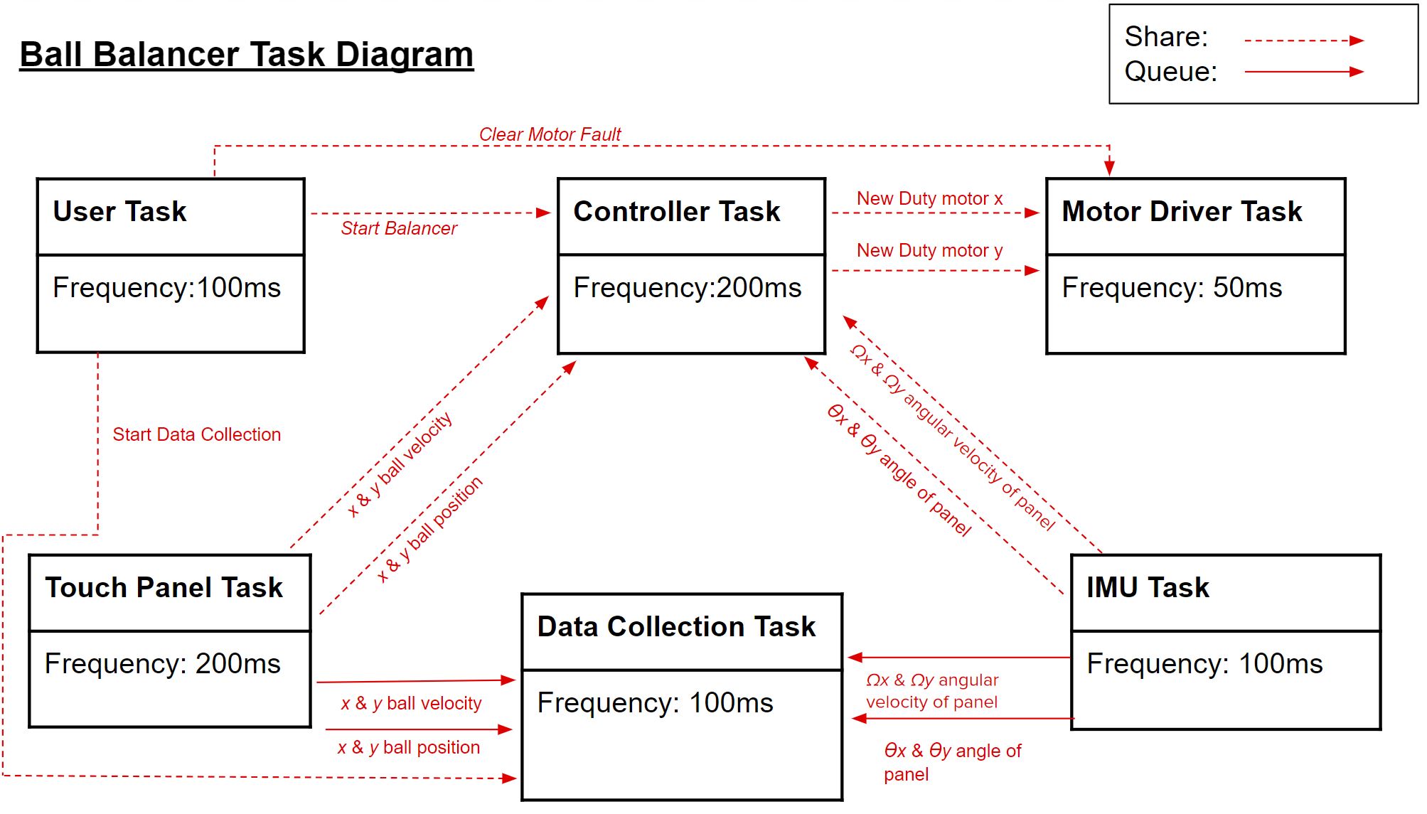
Thus, pictured below is a task diagram that shows how the variables get shared through out our code. There are 6 total tasks that will tell each of their respective driver files to do something. As you can see, the closedloop task is the one that takes in the ball position, panel angle, ball velocity, and panel angular velocity and spits out a new duty cycle for the motors to run and to counter act the movement of the ball.
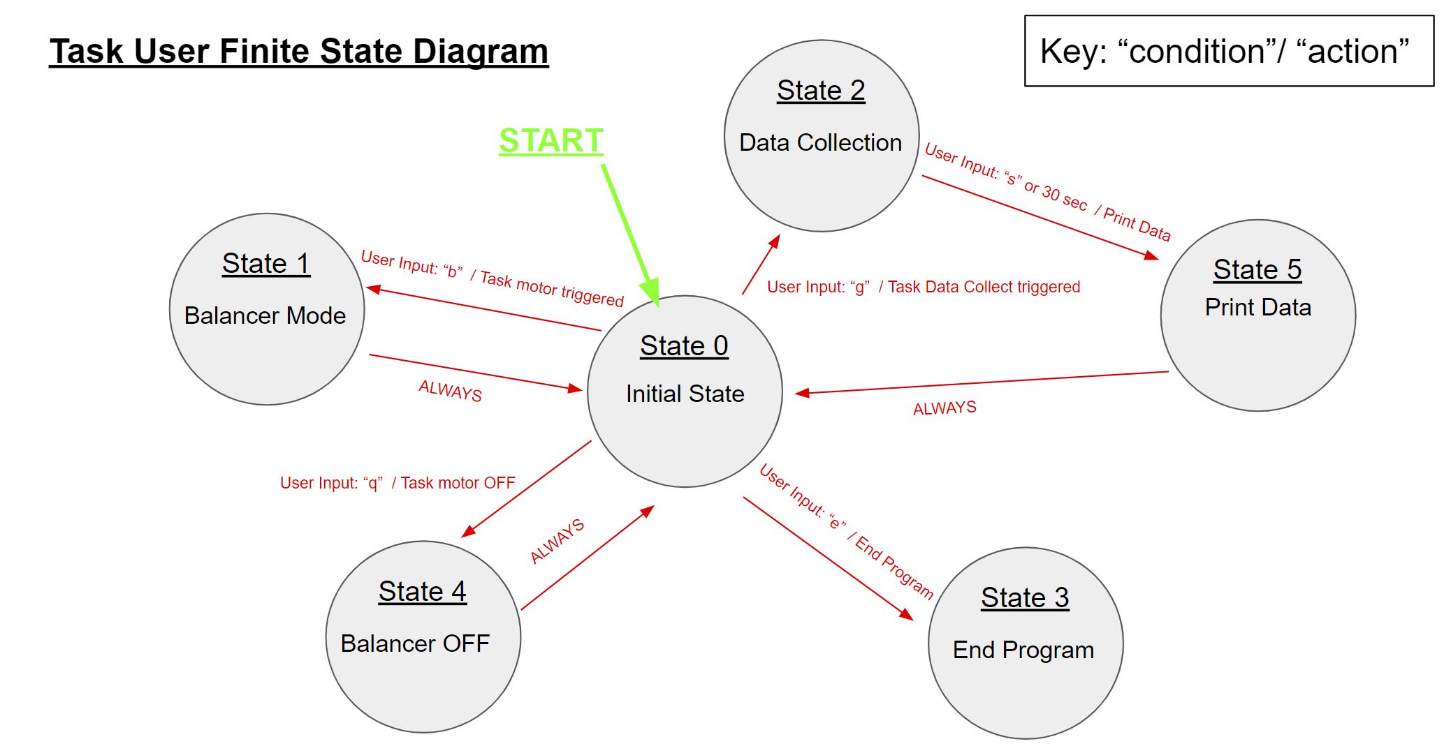
Finally here is a finite state diagram that depicts how our user interface is set up with its various states. Basically the user can choose to turn on/off the balancer,to collect data,to end data collection prematurily, and to end the program at any time.
Here is a video depicting the final performance of our set-up:
The performance is not obviously not up to par, there is a constant battle between choosing a high enough controller gain that will implement a high enough duty cycle to the motors, but not so high it over compensates and becomes unstable. There was a total of 8 controller gains, 4 used on each motor, that multiply with the current ball position, angle of panel, ball velocity, and angular velocity of the panel.